|
The arrangement of the bolt holes on steel profiles usually follows a rectangular pattern. In other words, the holes are in rows. The holes in one row are in line with the holes in the other rows, as shown in Figure 1.70 on the following page. This makes for easier setting out and a neat appearance.
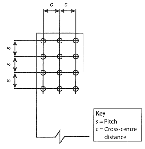
Figure 1.70
Rectangular layout of bolts
The spacing between bolts in the longitudinal direction of a member is called the pitch. The spacing at right angles to this is called the cross-centre distance. The minimum and maximum pitches and cross-centres allowed from a design point of view are laid down in SANS 10162-1, but minimum spacings are also controlled by the clearance required between the head of the spanner or wrench and the nearest bolt already installed.
When the bolts in alternate rows are offset from those in intermediate rows, they are said to be in a staggered pattern, as shown in Figure 1.71 This pattern is used when a large number of bolts are to be fitted into a limited width, since the zigzag arrangement allows the bolts to be more closely nestled whilst still maintaining the required minimum centre-to-centre distance, d.
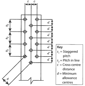
Figure 1.71
Staggered layout of bolts
However, the length of the bolt group is increased. It should also be noted that, for quality-control reasons, this staggered pattern is not recommended.
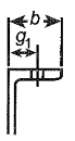
Holes in the flanges of I- and H-sections and channels and the legs of angles are usually placed on the centre lines at a set distance from the backs of channels or angles (gauge hnes or back mark lines) or from the web centres of I- and H-sections (gauge lines or cross-centre lines).
Table 1.17 shows the recommended gauges and back marks for channel sections. It also gives the maximum hole diameter that should be used for each section flange width.
|
Recommended gauges and back marks for channel sections
|
|
|
|
b
(mm)
|
g1
(mm)
|
Ø max.
(mm)
|
|
38
|
22
|
8
|
|
45
|
25
|
10
|
|
50
|
28
|
12
|
|
54,55
|
28
|
16
|
|
60
|
35
|
16
|
|
64,65
|
35
|
20
|
|
70
|
40
|
20
|
|
75-85
|
45
|
20
|
|
90
|
50
|
24
|
|
95-110
|
55
|
24
|
Table 1.17
Recommended gauges and back marks for channel sections
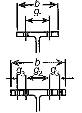
Table 1.18 shows the recommended gauges and back marks for I- and H-sections. It also gives the maximum hole diameter that should be used for each section flange width.
|
Recommended gauges and back marks for I- and H-sections
|
|
|
|
b
(mm)
|
Gauge (mm)
|
Ø max.
(mm)
|
|
g1
|
g2
|
g3
|
|
64
|
32
|
|
|
12
|
|
73-82
|
40
|
12
|
|
89-91
|
50
|
12
|
|
102
|
54
|
16
|
|
133-146
|
70
|
20
|
|
152
|
90
|
20
|
|
165-191
|
90
|
24
|
|
203-254
|
140
|
24
|
|
305
|
140
|
120
|
60
|
24
|
|
368-406
|
140
|
140
|
75
|
24
|
Table 1.18
Recommended gauges and back marks for 1- and H-sections
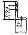
Table 1.19 shows the recommended gauges and back marks for angles. It also gives the maximum hole diameter that should be used for each section flange width.
|
Recommended gauges and back marks for angles
|
|
|
|
h or b
(mm)
|
Back mark g1
(mm)
|
Ø max.
(mm)
|
h or b
(mm)
|
Back mark (mm)
|
h or b
(mm)
|
|
g1
|
g2
|
g3
|
g4
|
|
25
|
15
|
|
90
|
50
|
|
|
|
24
|
|
30
|
17
|
|
100
|
50
|
|
|
|
24
|
|
35
|
20
|
|
120
|
60
|
|
|
|
24
|
|
40
|
22
|
8
|
120
|
|
45
|
45
|
|
16
|
|
45
|
25
|
10
|
125
|
65
|
|
|
|
24
|
|
50
|
28
|
12
|
125
|
|
45
|
45
|
|
20
|
|
60
|
35
|
16
|
150
|
75
|
|
|
|
24
|
|
65
|
35
|
20
|
150
|
|
55
|
55
|
|
20
|
|
70
|
40
|
20
|
200
|
|
75
|
75
|
|
24
|
|
75
|
45
|
20
|
200
|
|
55
|
55
|
55
|
20
|
|
80
|
45
|
20
|
200
|
|
|
|
|
|
Table 1.19
Recommended gauges and back marks for angles
The distances for the back marks are illustrated in details (a) to (c) of Figure
1.72. The set distances vary according to the size of the particular section, but are standard for each size of section.
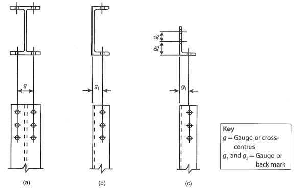
Figure 1.72
Layout of bolts
Another limitation on bolt placement is the distance of a hole from the edge of the plate or member. This is called the edge distance. When it is measured to the end and not the side of the member, it is called the end distance. Minimum limits are placed on this dimension to prevent tear-out of the plate edge when the shear force in the bolts is directed towards the edge.
These limits are specified in SANS 10162-1. Holes in the flanges of I- and H-sections are usually placed at a set distance from the web centres (gauge lines or cross-centre lines) or at a set distance from the backs of channels or angles (gauge lines or back mark lines). We refer to this set distance as the gauge distance.
|
 Resource Centre
 Student Stationery
 Media Centre
 Student Portal
 Refer to the student portal for additional resources related to this module.